Bewise Inc. www.tool-tool.com
Reference source from the internet.
For other uses, see Transformer
(disambiguation).

Pole-mounted single-phase transformer with center-tapped secondary. Note
use of the ground conductor as
one leg of the primary feeder.
A transformer is a device that transfers electrical energy from
one circuit to
another through inductively coupled
conductors — the transformer's coils or "windings". Except for air-core transformers,
the conductors are commonly wound around a single iron-rich core, or around
separate but magnetically-coupled cores. A varying current in the first or
"primary" winding creates a varying magnetic field in the
core (or cores) of the transformer. This varying magnetic field induces a
varying electromotive
force (EMF) or "voltage" in
the "secondary" winding. This effect is called mutual induction.
If a load is
connected to the secondary, an electric current will flow in the secondary
winding and electrical energy will flow from the primary circuit through the
transformer to the load. In an ideal transformer, the induced voltage in the
secondary winding (VS) is in proportion to the primary voltage
(VP), and is given by the ratio of the number of turns in the
secondary to the number of turns in the primary as follows:

By appropriate selection of the ratio of turns, a transformer thus allows an
alternating current
(AC) voltage to be "stepped up" by making NS greater than
NP, or "stepped down" by making NS less than
NP.
Transformers come in a range of sizes from a thumbnail-sized coupling
transformer hidden inside a stage microphone to huge units
weighing hundreds of tons used to interconnect portions of national power grids. All operate with
the same basic principles, although the range of designs is wide. While new
technologies have eliminated the need for transformers in some electronic
circuits, transformers are still found in nearly all electronic devices designed
for household ("mains")
voltage. Transformers are essential for high voltage power transmission,
which makes long distance transmission economically practical.
[edit]
History
[edit]
First steps: experiments with induction coils
What would become the "transformer principle" was revealed in 1831 by Michael Faraday in his
demonstration of electromagnetic
induction, but without recognition of its future role in manipulating EMF.
The first "induction
coils" to see wide use were invented by Rev. Nicholas Callan of
Maynooth College, Ireland in 1836, one of the first researchers to realize that
the more turns the secondary winding has in relation to the primary winding, the
larger the increase in EMF. Induction coils evolved from scientists' and
inventors' efforts to get higher voltages from batteries. Rather than alternating current (AC), their
action relied upon a vibrating "make-and-break" mechanism that regularly
interrupted the flow of direct current
(DC) from the batteries. Between the 1830s and the 1870s, efforts to build
better induction coils, mostly by trial and error, slowly revealed the basic
principles of transformers. Efficient, practical designs did not appear until
the 1880s,[1]
but within a decade the "transformer" would be instrumental in the "War of Currents", and in
seeing AC distribution systems triumph over their DC counterparts, a position in
which they have remained dominant ever since.[1]
In 1876, Russian engineer Pavel Yablochkov
invented a lighting system based on a set of induction coils where the primary
windings were connected to a source of alternating current and the secondary
windings could be connected to several "electric candles"
(arc lamps) of his own design.[2][3]
The coils used in the system behaved as primitive transformers.[2]
The patent claimed the system could "provide separate supply to several lighting
fixtures with different luminous intensities from a single source of electric
power".[citation
needed]
In 1878, the engineers of the Ganz Company in Hungary assigned part of its
extensive engineering works to the manufacture of electric lighting apparatus
for Austria-Hungary,
and by 1883 made over fifty installations. It offered an entire system
consisting of both arc and
incandescent lamps,
generators, and other accessories.[4]
Lucien Gaulard and
John
Dixon Gibbs first exhibited a device with an open iron core called a
"secondary generator" in London in 1882, then sold the
idea to the Westinghouse
company in the United
States.[5]
They also exhibited the invention in Turin, Italy in 1884, where it was
adopted for an electric lighting system.
Induction coils with open magnetic circuits are inefficient for transfer of
power to loads.
Various methods of adjusting the cores or bypassing magnetic flux around part of
a coil were developed, since until about 1880 the paradigm for AC power
transmission from a high voltage supply to a low voltage load was a series
circuit. In practice, several coils with a ratio near 1:1 were connected with
their primaries in series to allow use of a high voltage for transmission while
presenting a low voltage to the lamps. The inherent flaw in this method was that
turning off a single lamp affected all the others on the circuit, and many
adjustable coil designs were introduced in an effort to accommodate this
problematic characteristic of the series circuit.[6]
[edit]
First transformers

Stanley's 1886 transformer, a redesigned commercial version of the earlier
Hungarian "ZBD" transformer
Between 1884 and 1885, Hungarian engineers Zipernowsky, Bláthy and Déri from the Ganz company in Budapest created the efficient
"ZBD" closed-core model, which were based on the design by Gaulard and Gibbs.
(Gaulard and Gibbs designed just an open core model) [7][8] They
discovered that all former (coreless or open-core) devices were incapable of
regulating voltage, and were therefore impracticable. Their joint patent
described a transformer with no poles and comprised two versions of it, the
"closed-core transformer" and the "shell-core transformer. In the closed-core
transformer the iron core is a closed ring around which the two coils are
arranged uniformly. In the shell type transformer, the copper induction cables
are passed through the core. In both designs, the magnetic flux linking the
primary and secondary coils travels (almost entirely) in the iron core, with no
intentional path through air. The core consists of iron cables or plates. Based
on this invention, it became possible to provide economical and cheap lighting
for industry and households."[9] Zipernowsky, Bláthy and Déri discovered the
mathematical formula of transformers: Vs/Vp = Ns/Np.[citation
needed] With this formula, transformers became calculable and
proportionable. Their patent application made the first use of the word
"transformer", a word that had been coined by Ottó
Bláthy.[10]
George Westinghouse had bought both Gaulard and Gibbs' and the "ZBD" patents in
1885. He entrusted William
Stanley with the building of a ZBD-type transformer for commercial
use.[11]
Stanley built the core from interlocking E-shaped iron plates. This design was
first used commercially in 1886.[1]
[edit]
Early developments and applications
Russian engineer Mikhail
Dolivo-Dobrovolsky developed the first three-phase transformer in
1889. In 1891 Nikola
Tesla invented the Tesla
coil, an air-cored, dual-tuned resonant transformer for generating very high voltages at high
frequency. Audio
frequency transformers (at the time called repeating coils) were
used by the earliest experimenters in the development of the telephone.
[edit]
Basic principles
The transformer is based on two principles: firstly, that an electric current can
produce a magnetic
field (electromagnetism) and
secondly that a changing magnetic field within a coil of wire induces a voltage
across the ends of the coil (electromagnetic
induction). Changing the current in the primary coil changes the magnitude
of the applied magnetic field. The changing magnetic flux extends to the
secondary coil where a voltage is induced across its ends.
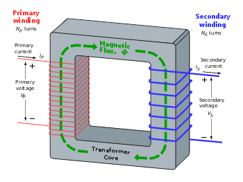
An ideal step-down
transformer showing magnetic flux in the core.
A simplified transformer design is shown to the left. A current passing
through the primary coil creates a magnetic field. The
primary and secondary coils are wrapped around a core of very high magnetic
permeability, such as iron;
this ensures that most of the magnetic field lines produced by the primary
current are within the iron and pass through the secondary coil as well as the
primary coil.
[edit]
Induction law
The voltage induced across the secondary coil may be calculated from Faraday's law
of induction, which states that:
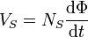
where VS is the instantaneous voltage,
NS is the number of turns in the secondary coil and
Φ equals the magnetic flux through one
turn of the coil. If the turns of the coil are oriented perpendicular to the
magnetic field lines, the flux is the product of the magnetic field strength
B and the area A through which it cuts. The area is constant,
being equal to the cross-sectional area of the transformer core, whereas the
magnetic field varies with time according to the excitation of the primary.
Since the same magnetic flux passes through both the primary and secondary coils
in an ideal transformer,[12]
the instantaneous voltage across the primary winding equals

Taking the ratio of the two equations for VS and
VP gives the basic equation[13]
for stepping up or stepping down the voltage
[edit]
Ideal power equation

The ideal transformer as a circuit element
If the secondary coil is attached to a load that allows current to flow,
electrical power is transmitted from the primary circuit to the secondary
circuit. Ideally, the transformer is perfectly efficient; all the incoming
energy is transformed from the primary circuit to the magnetic field and into
the secondary circuit. If this condition is met, the incoming electric power must equal
the outgoing power.
- Pincoming =
IPVP =
Poutgoing =
ISVS
giving the ideal transformer equation
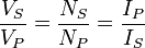
If the voltage is increased (stepped up) (VS >
VP), then the current is decreased (stepped down)
(IS < IP) by the same factor.
Transformers are efficient so this formula is a reasonable approximation.
The impedance in one circuit is transformed by the square of the turns
ratio.[12]
For example, if an impedance ZS is attached across the
terminals of the secondary coil, it appears to the primary circuit to have an
impedance of  .
This relationship is reciprocal, so that the impedance ZP of
the primary circuit appears to the secondary to be
.
This relationship is reciprocal, so that the impedance ZP of
the primary circuit appears to the secondary to be  .
.
[edit]
Detailed operation
The simplified description above neglects several practical factors, in
particular the primary current required to establish a magnetic field in the
core, and the contribution to the field due to current in the secondary circuit.
Models of an ideal transformer typically assume a core of negligible reluctance with two
windings of zero resistance.[14]
When a voltage is applied to the primary winding, a small current flows, driving
flux around the magnetic circuit of the
core.[14].
The current required to create the flux is termed the magnetizing
current; since the ideal core has been assumed to have near-zero reluctance,
the magnetizing current is negligible, although still required to create the
magnetic field.
The changing magnetic field induces an electromotive force
(EMF) across each winding.[15]
Since the ideal windings have no impedance, they have no associated voltage
drop, and so the voltages VP and VS measured at the
terminals of the transformer, are equal to the corresponding EMFs. The primary
EMF, acting as it does in opposition to the primary voltage, is sometimes termed
the "back
EMF".[16]
This is due to Lenz's
law which states that the induction of EMF would always be such that it will
oppose development of any such change in magnetic field.
[edit]
Practical considerations
[edit]
Leakage flux
Leakage flux of a transformer
Main article: Leakage inductance
The ideal transformer model assumes that all flux generated by the primary
winding links all the turns of every winding, including itself. In practice,
some flux traverses paths that take it outside the windings.[17]
Such flux is termed leakage flux, and results in leakage inductance in
series
with the mutually coupled transformer windings.[16]
Leakage results in energy being alternately stored in and discharged from the magnetic fields with each
cycle of the power supply. It is not directly a power loss (see "Stray losses" below),
but results in inferior voltage regulation,
causing the secondary voltage to fail to be directly proportional to the
primary, particularly under heavy load.[17]
Transformers are therefore normally designed to have very low leakage inductance.
However, in some applications, leakage can be a desirable property, and long
magnetic paths, air gaps, or magnetic bypass shunts may be deliberately
introduced to a transformer's design to limit the short-circuit current it
will supply.[16]
Leaky transformers may be used to supply loads that exhibit negative resistance,
such as electric arcs,
mercury vapor
lamps, and neon signs;
or for safely handling loads that become periodically short-circuited such as electric arc welders.[18] Air
gaps are also used to keep a transformer from saturating, especially
audio-frequency transformers in circuits that have a direct current flowing
through the windings.
[edit]
Effect of frequency
The time-derivative term in Faraday's
Law shows that the flux in the core is the integral of the applied
voltage.[19]
Hypothetically an ideal transformer would work with direct-current excitation,
with the core flux increasing linearly with time.[20]
In practice, the flux would rise to the point where magnetic
saturation of the core occurred, causing a huge increase in the magnetizing
current and overheating the transformer. All practical transformers must
therefore operate with alternating (or pulsed) current.[20]
Transformer universal EMF equation
If the flux in the core is sinusoidal, the relationship
for either winding between its rms Voltage of the
winding E, and the supply frequency f, number of turns N,
core cross-sectional area a and peak magnetic flux
density B is given by the universal EMF equation:[14]

The EMF of a transformer at a given flux density increases with
frequency.[14]
By operating at higher frequencies, transformers can be physically more compact
because a given core is able to transfer more power without reaching saturation,
and fewer turns are needed to achieve the same impedance. However properties
such as core loss and conductor skin effect also increase
with frequency. Aircraft and military equipment employ 400 Hz power supplies
which reduce core and winding weight.[21]
Operation of a transformer at its designed voltage but at a higher frequency
than intended will lead to reduced magnetizing current; at lower frequency, the
magnetizing current will increase. Operation of a transformer at other than its
design frequency may require assessment of voltages, losses, and cooling to
establish if safe operation is practical. For example, transformers may need to
be equipped with "volts per hertz" over-excitation relays to protect the transformer
from overvoltage at higher than rated frequency.
Knowledge of natural frequencies of transformer windings is of importance for
the determination of the transient response of the windings to impulse and
switching surge voltages.
[edit]
Energy losses
An ideal transformer would have no energy losses, and would be 100%
efficient. In practical transformers energy is dissipated in the windings, core,
and surrounding structures. Larger transformers are generally more efficient,
and those rated for electricity distribution usually perform better than
98%.[22]
Experimental transformers using superconducting
windings achieving efficiencies of 99.85%,[23]
While the increase in efficiency is small, when applied to large heavily-loaded
transformers the annual savings in energy losses are significant.
A small transformer, such as a plug-in "wall-wart" or power adapter
type used for low-power consumer electronics, may be no more than 85% efficient,
with considerable loss even when not supplying any load. Though individual power
loss is small, the aggregate losses from the very large number of such devices
is coming under increased scrutiny.[24]
The losses vary with load current, and may be expressed as "no-load" or
"full-load" loss. Winding resistance
dominates load losses, whereas hysteresis and eddy currents losses
contribute to over 99% of the no-load loss. The no-load loss can be significant,
meaning that even an idle transformer constitutes a drain on an electrical
supply, which encourages development of low-loss transformers (also see energy
efficient transformer).[25]
Transformer losses are divided into losses in the windings, termed copper loss, and those in
the magnetic circuit, termed iron loss. Losses in the
transformer arise from:
- Winding resistance
- Current flowing through the windings causes resistive heating of
the conductors. At higher frequencies, skin effect and proximity
effect create additional winding resistance and losses.
- Hysteresis losses
- Each time the magnetic field is reversed, a small amount of energy is lost
due to hysteresis within
the core. For a given core material, the loss is proportional to the frequency,
and is a function of the peak flux density to which it is subjected.[25]
- Eddy currents
- Ferromagnetic
materials are also good conductors, and a
solid core made from such a material also constitutes a single short-circuited
turn throughout its entire length. Eddy currents therefore
circulate within the core in a plane normal to the flux, and are responsible for
resistive heating
of the core material. The eddy current loss is a complex function of the square
of supply frequency and inverse square of the material thickness.[25]
- Magnetostriction
- Magnetic flux in a ferromagnetic material, such as the core, causes it to
physically expand and contract slightly with each cycle of the magnetic field,
an effect known as magnetostriction. This
produces the buzzing sound commonly associated with transformers,[13]
and in turn causes losses due to frictional heating in susceptible cores.
- Mechanical losses
- In addition to magnetostriction, the alternating magnetic field causes
fluctuating electromagnetic forces between the primary and secondary windings.
These incite vibrations within nearby metalwork, adding to the buzzing noise, and consuming a
small amount of power.[26]
- Stray losses
-
- Leakage inductance is by itself lossless, since energy supplied to its
magnetic fields is returned to the supply with the next half-cycle. However, any
leakage flux that intercepts nearby conductive materials such as the
transformer's support structure will give rise to eddy currents and be converted
to heat.[27]
[edit]
Equivalent circuit
- Refer to the diagram below
The physical limitations of the practical transformer may be brought together
as an equivalent circuit model (shown below) built around an ideal lossless
transformer.[28]
Power loss in the windings is current-dependent and is represented as in-series
resistances RP and RS. Flux leakage results
in a fraction of the applied voltage dropped without contributing to the mutual
coupling, and thus can be modeled as reactances of each leakage inductance
XP and XS in series with the
perfectly-coupled region.
Iron losses are caused mostly by hysteresis and eddy current effects in the
core, and are proportional to the square of the core flux for operation at a
given frequency.[29]
Since the core flux is proportional to the applied voltage, the iron loss can be
represented by a resistance RC in parallel with the ideal
transformer.
A core with finite permeability
requires a magnetizing current IM to maintain the mutual flux
in the core. The magnetizing current is in phase with the flux; saturation
effects cause the relationship between the two to be non-linear, but for
simplicity this effect tends to be ignored in most circuit equivalents.[29]
With a sinusoidal supply,
the core flux lags the induced EMF by 90° and this effect can be modeled as a
magnetizing reactance (reactance of an effective inductance)
XM in parallel
with the core loss component. RC and XM are
sometimes together termed the magnetizing branch of the model. If the
secondary winding is made open-circuit, the current I0 taken
by the magnetizing branch represents the transformer's no-load
current.[28]
The secondary impedance
RS and XS is frequently moved (or
"referred") to the primary side after multiplying the components by the
impedance scaling factor  .
.

Transformer equivalent circuit, with secondary impedances referred to the
primary side
The resulting model is sometimes termed the "exact equivalent circuit",
though it retains a number of approximations, such as an assumption of linearity.[28]
Analysis may be simplified by moving the magnetizing branch to the left of the
primary impedance, an implicit assumption that the magnetizing current is low,
and then summing primary and referred secondary impedances, resulting in
so-called equivalent impedance.
The parameters of equivalent circuit of a transformer can be calculated from
the results of two transformer tests: open-circuit test and
short-circuit
test.
For more details on this topic, see Transformer types.
A wide variety of transformer designs are used for different applications,
though they share several common features. Important common transformer types
include:
[edit]
Autotransformer
Main article: Autotransformer

An autotransformer
with a sliding brush contact
An autotransformer
has only a single winding with two end terminals, plus a third at an
intermediate tap point. The primary voltage is applied across two of the
terminals, and the secondary voltage taken from one of these and the third
terminal. The primary and secondary circuits therefore have a number of windings
turns in common.[30]
Since the volts-per-turn is the same in both windings, each develops a voltage
in proportion to its number of turns. An adjustable autotransformer is made by
exposing part of the winding coils and making the secondary connection through a
sliding brush,
giving a variable turns ratio. [31]
[edit]
Polyphase transformers
For more details on this topic, see Three-phase
electric power.

Three-phase step-down transformer mounted between two utility poles.
For three-phase
supplies, a bank of three individual single-phase transformers can be used, or
all three phases can be incorporated as a single three-phase transformer. In
this case, the magnetic circuits are connected together, the core thus
containing a three-phase flow of flux.[32]
A number of winding configurations are possible, giving rise to different
attributes and phase
shifts.[33] One
particular polyphase configuration is the zigzag transformer,
used for grounding and
in the suppression of harmonic currents.[34]
[edit]
Leakage transformers

Leakage transformer
A leakage transformer, also called a stray-field transformer, has a
significantly higher leakage inductance
than other transformers, sometimes increased by a magnetic bypass or shunt in
its core between primary and secondary, which is sometimes adjustable with a set
screw. This provides a transformer with an inherent current limitation due to
the loose coupling between its primary and the secondary windings. The output
and input currents are low enough to prevent thermal overload under all load
conditions – even if the secondary is shorted.
Leakage transformers are used for arc welding and high voltage
discharge lamps (neon lamps
and cold
cathode fluorescent lamps, which are series-connected up to 7.5 kV AC). It
acts then both as a voltage transformer and as a magnetic
ballast.
Other applications are short-circuit-proof extra-low voltage transformers for
toys or doorbell
installations.
[edit]
Resonant transformers
A resonant
transformer is a kind of the leakage transformer. It uses the leakage inductance of
its secondary windings in combination with external capacitors, to create one or
more resonant
circuits. Resonant transformers such as the Tesla coil can generate very
high voltages, and are able to provide much higher current than electrostatic
high-voltage generation machines such as the Van de Graaff
generator.[35] One
of the applications of the resonant transformer is for the CCFL inverter. Another
application of the resonant transformer is to couple between stages of a superheterodyne
receiver, where the selectivity of the receiver is provided by tuned
transformers in the intermediate-frequency amplifiers.[36]
[edit]
Audio transformers
Main article: Transformer
types#Audio transformers
Audio transformers are those specifically designed for use in audio circuits.
They can be used to block radio frequency interference or the DC component of an
audio signal, to split or combine audio signals, or to provide impedance
matching between high and low impedance circuits, such as between a high
impedance tube (valve)
amplifier output and a low impedance loudspeaker, or between a
high impedance instrument output and the low impedance input of a mixing console.
Such transformers were originally designed to connect different telephone
systems to one another while keeping their respective power supplies isolated,
and are still commonly used to interconnect professional audio
systems or system components.
Being magnetic devices, audio transformers are susceptible to external
magnetic fields such as those generated by AC current-carrying conductors. "Hum"
is a term commonly used to describe unwanted signals originating from the "mains" power supply
(typically 50 or 60 Hz). Audio transformers used for low-level signals, such as
those from microphones, often included shielding to protect against extraneous
magnetically-coupled signals.
[edit]
Instrument transformers
Instrument transformers are used for measuring voltge,current,
power and energy in electrical systems, and for protection and
control. Where a voltage or current is too large to be conveniently measured by
an instrument, it can be scaled down to a standardized low value. Instrument
transformers isolate measurement and control circuitry from the high currents or
voltages present on the circuits being measured or controlled.

Current transformers, designed for placing around conductors
A current
transformer is a transformer designed to provide a current in its secondary
coil proportional to the current flowing in its primary coil. [37]
Voltage transformers (VTs), also referred to as "potential transformers"
(PTs), are used in high-voltage circuits. They are designed to present a
negligible load to the supply being measured, to allow protective relay
equipment to be operated at a lower voltages, and to have a precise winding
ratio for accurate metering.[38]
[edit]
Classification
Transformers can be classified in different ways:
- By power capacity: from a fraction of a volt-ampere (VA) to over a
thousand MVA;
- By frequency range: power-, audio-, or radio frequency;
- By voltage class: from a few volts to hundreds of kilovolts;
- By cooling type: air cooled, oil filled, fan cooled, or water cooled;
- By application: such as power supply, impedance matching, output
voltage and current stabilizer, or circuit isolation;
- By end purpose: distribution,
rectifier, arc furnace, amplifier
output;
- By winding turns ratio: step-up, step-down, isolating (equal or
near-equal ratio), variable.
[edit]
Construction

Laminated core transformer showing edge of laminations at top of unit.
[edit]
Laminated steel cores
Transformers for use at power or audio frequencies typically have cores made
of high permeability
silicon steel.[39]
The steel has a permeability many times that of free space, and the core thus
serves to greatly reduce the magnetizing current, and confine the flux to a path
which closely couples the windings.[40]
Early transformer developers soon realized that cores constructed from solid
iron resulted in prohibitive eddy-current losses, and their designs mitigated
this effect with cores consisting of bundles of insulated iron wires.[5]
Later designs constructed the core by stacking layers of thin steel laminations,
a principle that has remained in use. Each lamination is insulated from its
neighbors by a thin non-conducting layer of insulation.[32]
The universal
transformer equation indicates a minimum cross-sectional area for the core
to avoid saturation.
The effect of laminations is to confine eddy currents to highly elliptical
paths that enclose little flux, and so reduce their magnitude. Thinner
laminations reduce losses,[39]
but are more laborious and expensive to construct.[41]
Thin laminations are generally used on high frequency transformers, with some
types of very thin steel laminations able to operate up to 10 kHz.

Laminating the core greatly reduces eddy-current losses
One common design of laminated core is made from interleaved stacks of E-shaped steel sheets capped
with I-shaped pieces,
leading to its name of "E-I transformer".[41]
Such a design tends to exhibit more losses, but is very economical to
manufacture. The cut-core or C-core type is made by winding a steel strip around
a rectangular form and then bonding the layers together. It is then cut in two,
forming two C shapes, and the core assembled by binding the two C halves
together with a steel strap.[41]
They have the advantage that the flux is always oriented parallel to the metal
grains, reducing reluctance.
A steel core's remanence
means that it retains a static magnetic field when power is removed. When power
is then reapplied, the residual field will cause a high inrush current until the
effect of the remaining magnetism is reduced, usually after a few cycles of the
applied alternating current.[42]
Overcurrent protection devices
such as fuses
must be selected to allow this harmless inrush to pass. On transformers
connected to long, overhead power transmission lines, induced currents due to geomagnetic
disturbances during solar storms can cause
saturation of the core and operation of transformer protection devices.[43]
Distribution transformers can achieve low no-load losses by using cores made
with low-loss high-permeability silicon steel or amorphous
(non-crystalline) metal alloy. The higher initial cost of the core material
is offset over the life of the transformer by its lower losses at light
load.[44]
[edit]
Solid cores
Powdered iron cores are used
in circuits (such as switch-mode power supplies) that operate above main
frequencies and up to a few tens of kilohertz. These materials combine high
magnetic permeability
with high bulk electrical resistivity. For frequencies
extending beyond the VHF band, cores made
from non-conductive magnetic ceramic materials called ferrites are
common.[41]
Some radio-frequency transformers also have movable cores (sometimes called
'slugs') which allow adjustment of the coupling coefficient (and bandwidth)
of tuned radio-frequency circuits.
[edit]
Toroidal cores

Small toroidal core transformer
Toroidal transformers are built around a ring-shaped core, which, depending
on operating frequency, is made from a long strip of silicon steel or permalloy wound into a coil,
powdered iron, or ferrite.[45] A
strip construction ensures that the grain boundaries are
optimally aligned, improving the transformer's efficiency by reducing the core's
reluctance. The closed
ring shape eliminates air gaps inherent in the construction of an E-I
core.[46] The
cross-section of the ring is usually square or rectangular, but more expensive
cores with circular cross-sections are also available. The primary and secondary
coils are often wound concentrically to cover the entire surface of the core.
This minimizes the length of wire needed, and also provides screening to
minimize the core's magnetic field from generating electromagnetic
interference.
Toroidal transformers are more efficient than the cheaper laminated E-I types
for a similar power level. Other advantages compared to E-I types, include
smaller size (about half), lower weight (about half), less mechanical hum
(making them superior in audio amplifiers), lower exterior magnetic field (about
one tenth), low off-load losses (making them more efficient in standby
circuits), single-bolt mounting, and greater choice of shapes. The main
disadvantages are higher cost and limited power capacity (see "Classification"
above).
Ferrite toroidal cores are used at higher frequencies, typically between a
few tens of kilohertz to a megahertz, to reduce losses, physical size, and
weight of switch-mode power
supplies. A drawback of toroidal transformer construction is the higher cost
of windings. As a consequence, toroidal transformers are uncommon above ratings
of a few kVA. Small distribution transformers may achieve some of the benefits
of a toroidal core by splitting it and forcing it open, then inserting a bobbin
containing primary and secondary windings.
[edit]
Air cores
A physical core is not an absolute requisite and a functioning transformer
can be produced simply by placing the windings in close proximity to each other,
an arrangement termed an "air-core" transformer. The air which comprises the
magnetic circuit is essentially lossless, and so an air-core transformer
eliminates loss due to hysteresis in the core
material.[16]
The leakage inductance is inevitably high, resulting in very poor regulation,
and so such designs are unsuitable for use in power distribution.[16]
They have however very high bandwidth,
and are frequently employed in radio-frequency applications,[47] for
which a satisfactory coupling coefficient is maintained by carefully overlapping
the primary and secondary windings.
[edit]
Windings

Windings are usually arranged concentrically to minimize flux leakage

Cut view through transformer windings. White: insulator. Green spiral: Grain oriented silicon
steel. Black: Primary winding made of oxygen-free copper.
Red: Secondary winding. Top left: Toroidal transformer. Right: C-core, but
E-core would be similar. The black windings are made of film. Top: Equally low
capacitance between all ends of both windings. Since most cores are at least
moderately conductive they also need insulation. Bottom: Lowest capacitance for
one end of the secondary winding needed for low-power high-voltage transformers.
Bottom left: Reduction of leakage inductance
would lead to increase of capacitance.
The conducting
material used for the windings depends upon the application, but in all
cases the individual turns must be electrically insulated from each other to
ensure that the current travels throughout every turn.[19]
For small power and signal transformers, in which currents are low and the
potential difference between adjacent turns is small, the coils are often wound
from enamelled magnet
wire, such as Formvar wire. Larger power transformers operating at high
voltages may be wound with copper rectangular strip conductors insulated by
oil-impregnated paper and blocks of pressboard.[48]
High-frequency transformers operating in the tens to hundreds of kilohertz
often have windings made of braided litz wire to
minimize the skin-effect and proximity
effect losses.[19]
Large power transformers use multiple-stranded conductors as well, since even at
low power frequencies non-uniform distribution of current would otherwise exist
in high-current windings.[48]
Each strand is individually insulated, and the strands are arranged so that at
certain points in the winding, or throughout the whole winding, each portion
occupies different relative positions in the complete conductor. The
transposition equalizes the current flowing in each strand of the conductor, and
reduces eddy current losses in the winding itself. The stranded conductor is
also more flexible than a solid conductor of similar size, aiding
manufacture.[48]
For signal transformers, the windings may be arranged in a way to minimize
leakage inductance and stray capacitance to improve high-frequency response.
This can be done by splitting up each coil into sections, and those sections
placed in layers between the sections of the other winding. This is known as a
stacked type or interleaved winding.
Both the primary and secondary windings on power transformers may have
external connections, called taps, to
intermediate points on the winding to allow selection of the voltage ratio. The
taps may be connected to an automatic on-load tap changer for voltage
regulation of distribution circuits. Audio-frequency transformers, used for the
distribution of audio to public address loudspeakers, have taps to allow
adjustment of impedance to each speaker. A center-tapped transformer is
often used in the output stage of an audio power amplifier in a push-pull circuit.
Modulation transformers in AM transmitters are
very similar.
Certain transformers have the windings protected by epoxy resin. By impregnating the
transformer with epoxy under a vacuum, one can replace air
spaces within the windings with epoxy, thus sealing the windings and helping to
prevent the possible formation of corona and absorption of dirt or water. This
produces transformers more suited to damp or dirty environments, but at
increased manufacturing cost.[49]
[edit]
Coolant
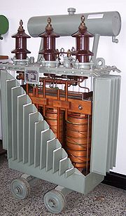
Cut away view of three-phase oil-cooled transformer. The oil reservoir is
visible at the top. Radiative fins aid the dissipation of heat.
High temperatures will damage the winding insulation. [50]
Small transformers do not generate significant heat and are cooled by air
circulation and radiation of heat. Power transformers rated up to several
hundred kVA can be adequately cooled by natural convective air-cooling,
sometimes assisted by fans.[51] In
larger transformers, part of the design problem is removal of heat. Some power
transformers are immersed in transformer oil that
both cools and insulates the windings.[52]
The oil is a highly refined mineral oil that remains
stable at transformer operating temperature. Indoor liquid-filled transformers
must use a non-flammable liquid, or must be located in fire resistant
rooms.[53]
Air-cooled dry transformers are preferred for indoor applications even at
capacity ratings where oil-cooled construction would be more economical, because
their cost is offset by the reduced building construction cost.
The oil-filled tank often has radiators through which the oil circulates by
natural convection; some large transformers employ forced circulation of the oil
by electric pumps, aided by external fans or water-cooled heat exchangers.[52]
Oil-filled transformers undergo prolonged drying processes to ensure that the
transformer is completely free of water vapor before the
cooling oil is introduced. This helps prevent electrical breakdown under load.
Oil-filled transformers may be equipped with Buchholz relays, which
detect gas evolved during internal arcing and rapidly de-energize the
transformer to avert catastrophic failure.[42]
Polychlorinated
biphenyls have properties that once favored their use as a coolant, though
concerns over their environmental
persistence led to a widespread ban on their use.[54]
Today, non-toxic, stable silicone-based oils, or fluorinated hydrocarbons
may be used where the expense of a fire-resistant liquid offsets additional
building cost for a transformer vault.[50][53]
Before 1977, even transformers that were nominally filled only with mineral oils
may also have been contaminated with polychlorinated biphenyls at 10-20 ppm. Since mineral oil
and PCB fluid mix, maintenance equipment used for both PCB and oil-filled
transformers could carry over small amounts of PCB, contaminating oil-filled
transformers. [55]
Some "dry" transformers (containing no liquid) are enclosed in sealed,
pressurized tanks and cooled by nitrogen or sulfur hexafluoride
gas.[50].
Experimental power transformers in the 2 MVA range have been built with superconducting
windings which eliminates the copper losses, but not the core steel loss. These
are cooled by liquid
nitrogen or helium.[56]
[edit]
Terminals
Very small transformers will have wire leads connected directly to the ends
of the coils, and brought out to the base of the unit for circuit connections.
Larger transformers may have heavy bolted terminals, bus bars or high-voltage
insulated bushings made
of polymers or porcelain. A large bushing can be a complex structure since it
must provide careful control of the electric field
gradient without letting the transformer leak oil.[57]
[edit]
Applications
A major application of transformers is to increase voltage before transmitting
electrical energy over long distances through wires. Wires have resistance and so
dissipate electrical energy at a rate proportional to the square of the current
through the wire. By transforming electrical
power to a high-voltage (and therefore low-current) form for transmission
and back again afterwards, transformers enable economic transmission of
power over long distances. Consequently, transformers have shaped the electricity supply
industry, permitting generation to be
located remotely from points of demand.[58] All
but a tiny fraction of the world's electrical power has
passed through a series of transformers by the time it reaches the
consumer.[27]
Transformers are also used extensively in electronic products
to step down the supply voltage to a level suitable for
the low voltage circuits they contain. The transformer also electrically
isolates the end user from contact with the supply voltage.
Signal
and audio transformers are used
to couple stages of amplifiers and to match
devices such as microphones and record player s to the
input of amplifiers. Audio transformers allowed telephone circuits to carry on
a two-way conversation
over a single pair of wires. Transformers are also used when it is necessary to
couple a differential-mode
signal to a ground-referenced
signal, and for between external cables and internal circuits.
歡迎來到Bewise
Inc.的世界,首先恭喜您來到這接受新的資訊讓產業更有競爭力,我們是提供專業刀具製造商,應對客戶高品質的刀具需求,我們可以協助客戶滿足您對產業的不同要求,我們有能力達到非常卓越的客戶需求品質,這是現有相關技術無法比擬的,我們成功的滿足了各行各業的要求,包括:精密HSS
DIN切削刀具、協助客戶設計刀具流程、DIN or JIS 鎢鋼切削刀具設計、NAS986 NAS965 NAS897 NAS937orNAS907 航太切削刀具,NAS航太刀具設計、超高硬度的切削刀具、醫療配件刀具設計、複合式再研磨機、PCD地板專用企口鑽石組合刀具、NSK高數主軸與馬達、專業模具修補工具-氣動與電動、粉末造粒成型機、主機版專用頂級電桿、PCD
V-Cut刀、捨棄式圓鋸片組、粉末成型機、主機版專用頂級電感、’汽車業刀具設計、電子產業鑽石刀具、木工產業鑽石刀具、銑刀與切斷複合再研磨機、銑刀與鑽頭複合再研磨機、銑刀與螺絲攻複合再研磨機等等。我們的產品涵蓋了從民生刀具到工業級的刀具設計;從微細刀具到大型刀具;從小型生產到大型量產;全自動整合;我們的技術可提供您連續生產的效能,我們整體的服務及卓越的技術,恭迎您親自體驗!!
BW Bewise Inc. Willy Chen
willy@tool-tool.com
bw@tool-tool.com www.tool-tool.com
skype:willy_chen_bw mobile:0937-618-190 Head &Administration Office
No.13,Shiang Shang 2nd St., West Chiu Taichung,Taiwan 40356 http://www.tool-tool.com /
FAX:+886 4 2471 4839 N.Branch 5F,No.460,Fu Shin North Rd.,Taipei,Taiwan S.Branch
No.24,Sec.1,Chia Pu East Rd.,Taipao City,Chiayi Hsien,Taiwan
Welcome to BW tool
world! We are an experienced tool maker specialized in cutting tools. We focus
on what you need and endeavor to research the best cutter to satisfy
users’ demand. Our customers involve wide range of industries,
like mold & die, aerospace, electronic, machinery, etc. We are professional
expert in cutting field. We would like to solve every problem from you. Please
feel free to contact us, its our pleasure to serve for you. BW product including: cutting
tool、aerospace tool
.HSS DIN Cutting
tool、Carbide end
mills、Carbide cutting
tool、NAS Cutting
tool、NAS986 NAS965 NAS897 NAS937orNAS907 Cutting Tools,Carbide end mill、disc milling cutter,Aerospace cutting
tool、hss
drill’Фрезеры’Carbide drill、High speed steel、Compound Sharpener’Milling cutter、INDUCTORS FOR PCD’CVDD(Chemical Vapor Deposition Diamond
)’PCBN (Polycrystalline Cubic
Boron Nitride) ’Core
drill、Tapered end mills、CVD Diamond Tools Inserts’PCD Edge-Beveling Cutter(Golden
Finger’PCD
V-Cutter’PCD Wood
tools’PCD Cutting
tools’PCD Circular Saw
Blade’PVDD End
Mills’diamond
tool. INDUCTORS FOR PCD .
POWDER FORMING MACHINE
‘Single Crystal Diamond
‘Metric end
mills、Miniature end
mills、Специальные
режущие инструменты ‘Пустотелое сверло
‘Pilot
reamer、Fraises’Fresas con mango’ PCD (Polycrystalline
diamond) ‘Frese’POWDER FORMING
MACHINE’Electronics cutter、Step drill、Metal cutting saw、Double margin drill、Gun barrel、Angle milling cutter、Carbide burrs、Carbide tipped cutter、Chamfering tool、IC card engraving cutter、Side cutter、Staple Cutter’PCD diamond cutter specialized in grooving
floors’V-Cut PCD
Circular Diamond Tipped Saw Blade with Indexable Insert’ PCD Diamond Tool’ Saw Blade with Indexable
Insert’NAS
tool、DIN or
JIS tool、Special tool、Metal slitting saws、Shell end mills、Side and face milling
cutters、Side chip
clearance saws、Long end
mills’end mill
grinder’drill
grinder’sharpener、Stub roughing end mills、Dovetail milling cutters、Carbide slot drills、Carbide torus cutters、Angel carbide end mills、Carbide torus cutters、Carbide ball-nosed slot
drills、Mould cutter、Tool
manufacturer.
Bewise Inc. www.tool-tool.com
ようこそBewise Inc.の世界へお越し下さいませ、先ず御目出度たいのは新たな
情報を受け取って頂き、もっと各産業に競争力プラス展開。
弊社は専門なエンド・ミルの製造メーカーで、客先に色んな分野のニーズ、
豊富なパリエーションを満足させ、特にハイテク品質要求にサポート致します。
弊社は各領域に供給できる内容は:
(1)精密HSSエンド・ミルのR&D
(2)Carbide Cutting
tools設計
(3)鎢鋼エンド・ミル設計
(4)航空エンド・ミル設計
(5)超高硬度エンド・ミル
(6)ダイヤモンド・エンド・ミル
(7)医療用品エンド・ミル設計
(8)自動車部品&材料加工向けエンド・ミル設計
弊社の製品の供給調達機能は:
(1)生活産業~ハイテク工業までのエンド・ミル設計
(2)ミクロ・エンド・ミル~大型エンド・ミル供給
(3)小Lot生産~大量発注対応供給
(4)オートメーション整備調達
(5)スポット対応~流れ生産対応
弊社の全般供給体制及び技術自慢の総合専門製造メーカーに貴方のご体験を御待ちしております。
Bewise Inc. talaşlı imalat sanayinde en fazla kullanılan ve üç eksende
(x,y,z) talaş kaldırabilen freze takımlarından olan Parmak Freze imalatçısıdır.
Çok geniş ürün yelpazesine sahip olan firmanın başlıca ürünlerini Karbür Parmak
Frezeler, Kalıpçı Frezeleri, Kaba Talaş Frezeleri, Konik Alın Frezeler, Köşe
Radyüs Frezeler, İki Ağızlı Kısa ve Uzun Küresel Frezeler, İç Bükey Frezeler vb.
şeklinde sıralayabiliriz.
BW специализируется в
научных исследованиях и разработках, и снабжаем самым высокотехнологичным
карбидовым материалом для поставки режущих / фрезеровочных инструментов для
почвы, воздушного пространства и электронной индустрии. В нашу основную
продукцию входит твердый карбид / быстрорежущая сталь, а также двигатели,
микроэлектрические дрели, IC картонорезальные машины, фрезы для гравирования,
режущие пилы, фрезеры-расширители, фрезеры-расширители с резцом, дрели, резаки
форм для шлицевого вала / звездочки роликовой цепи, и специальные нано
инструменты. Пожалуйста, посетите сайт www.tool-tool.com для получения
большей информации.
BW is specialized in
R&D and sourcing the most advanced carbide material with high-tech coating
to supply cutting / milling tool for mould & die, aero space and electronic
industry. Our main products include solid carbide / HSS end mills, micro
electronic drill, IC card cutter, engraving cutter, shell end mills, cutting
saw, reamer, thread reamer, leading drill, involute gear cutter for spur wheel,
rack and worm milling cutter, thread milling cutter, form cutters for spline
shaft/roller chain sprocket, and special tool, with nano grade. Please visit our
web www.tool-tool.com
for more info.
文章定位: