Bewise Inc. www.tool-tool.com
Reference source from the internet.

Three-phase pole-mounted step-down transformer.
Trafo nyaéta hiji alat listrik nu kagunaannana pikeun mindahkeun énérgi
listrik ti hiji sirkuit
ka sirkuit séjénna ngaliwatan gulungan-gulungan kawat anu babarengan
diinduksi ku hiji medan magnét. Hiji trafo diwangun ku hiji inti (biasana
tina beusi) sarta dua gulungan
atawa leuwih nu dibeulitkeun kana inti. Arus bulak-balik dina
salasahiji gulungan ngabangkitkeun médan
magnét nu robah-robah dina jero intina, numana ahirna ngainduksi
(ngarangsang ngabangkitkeun) tegangan dina gulungan liana.
Trafo dipaké keur naékkeun atawa nurunkeun tegangan atawa arus listrik, keur
ngarobah impedansi,
sarta keur nyadiakeun isolasi listrik antar rangkéan.
[édit]
Sawangan
Artikel ieu keur dikeureuyeuh, ditarjamahkeun
tina basa
Inggris.
Bantosanna diantos kanggo narjamahkeun.
The transformer is one of the simplest of electrical devices. Its basic
design has not changed over the last one hundred years, yet transformer designs
and materials continue to be improved. Transformers are essential for high
voltage power
transmission, which makes long distance transmission economically practical.
This advantage was the principal factor in the selection of alternating
current power transmission in the "War
of Currents" in the late 1880s.
Audio
frequency transformers (at the time called repeating
coils) were used by the earliest experimenters in the development of the telephone.
While some electronics applications of the transformer have been made obsolete
by new technologies, transformers are still found in many electronic devices.
Transformers come in a range of sizes from a thumbnail-sized coupling
transformer hidden inside a stage microphone
to huge gigawatt
units used to interconnect large portions of national power
grids. All operate with the same basic principles and with many similarities
in their parts.
Gambar:Polemount-singlephase-closeup.jpg
Single phase pole-mounted step-down transformer
However, transformers are components of the systems that perform all these
functions.
[édit]
Analogi
The transformer may be considered as a simple two-wheel 'gearbox'
for electrical voltage and current. The primary winding is analogous to the
input shaft and the secondary winding to the output shaft. In this analogy,
current is equivalent to shaft speed, voltage to shaft torque.
In a gearbox, mechanical power (torque multiplied by speed) is constant
(neglecting losses) and is equivalent to electrical power (voltage multiplied by
current) which is also constant.
The gear
ratio is equivalent to the transformer step-up or step-down ratio. A step-up
transformer acts analogously to a reduction gear (in which mechanical power is
transferred from a small, rapidly rotating gear to a large, slowly rotating
gear): it trades current (speed) for voltage (torque), by transferring power
from a primary coil to a secondary coil having more turns. A step-down
transformer acts analogously to a multiplier gear (in which mechanical power is
transferred from a large gear to a small gear): it trades voltage (torque) for
current (speed), by transferring power from a primary coil to a secondary coil
having fewer turns.
[édit]
Prinsip dasar
[édit]
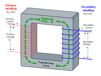
Coupling by mutual induction
A simple transformer consists of two electrical conductors
called the primary winding and the secondary winding. Energy is
coupled between the windings by the time-varying magnetic
flux that passes through (links) both primary and secondary windings.When
the current in a coil is switched on or off or changed, a voltage is induced in
a neighbouring coil. The effect, called mutual
inductance, is an example of electromagnetic induction.
[édit]
Analisis dasar
Practical transformer showing magnetising flux in the core
If a time-varying voltage  is applied to the primary winding of
  turns, a current will flow in it producing a magnetomotive
force (MMF). Just as an electromotive
force (EMF) drives current around an electric circuit, so MMF tries to drive
magnetic flux through a magnetic
circuit. The primary MMF produces a varying magnetic
flux
turns, a current will flow in it producing a magnetomotive
force (MMF). Just as an electromotive
force (EMF) drives current around an electric circuit, so MMF tries to drive
magnetic flux through a magnetic
circuit. The primary MMF produces a varying magnetic
flux  in the core, and, with an open circuit secondary winding, induces a back electromotive
force (EMF) in opposition to .
In accordance with Faraday's
law of induction, the voltage induced across the primary winding is
proportional to the rate of change of flux:
in the core, and, with an open circuit secondary winding, induces a back electromotive
force (EMF) in opposition to .
In accordance with Faraday's
law of induction, the voltage induced across the primary winding is
proportional to the rate of change of flux:
 and
and 
Saying that the primary and secondary windings are perfectly coupled is
equivalent to saying that  .
Substituting and solving for the voltages shows that:
.
Substituting and solving for the voltages shows that:

where
- vp and vs are voltages
across primary and secondary,
- Np and Ns are the numbers
of turns in the primary and secondary , respectively.
Hence in an ideal transformer, the ratio
of the primary and secondary voltages is equal to the ratio of the number
of turns in their windings, or alternatively, the voltage per turn is the
same for both windings. The ratio of the currents in the primary and secondary
circuits is inversely proportional to the turns ratio. This leads to the most
common use of the transformer: to convert electrical energy at one voltage to
energy at a different voltage by means of windings with different numbers of
turns. In a practical transformer, the higher-voltage winding will have more
turns, of smaller conductor cross-section, than the lower-voltage windings.
The EMF in the secondary winding, if connected to an electrical circuit, will
cause current to flow in the secondary circuit. The MMF produced by current in
the secondary opposes the MMF of the primary and so tends to cancel the flux in
the core. Since the reduced flux reduces the EMF induced in the primary winding,
increased current flows in the primary circuit. The resulting increase in MMF
due to the primary current offsets the effect of the opposing secondary MMF. In
this way, the electrical
energy fed into the primary winding is delivered to the secondary winding.
Also because of this, the flux density will always stay the same as long as the
primary voltage is steady.
For example, suppose a power
of 50 watts is supplied to a resistive load from a transformer with a turns
ratio of 25:2.
- P = EI (power = electromotive force × current)
-
- 50 W = 2 V × 25 A in the primary circuit if the load is a resistive load.
(See note 1)
- Now with transformer change:
-
- 50 W = 25 V × 2 A in the secondary circuit.
[édit]
Analisis trafo bulak-balik
This treats the windings
as a pair of mutually coupled coils with both primary
and secondary windings passing currents.
In an ideal transformer the primary MMF must equal the secondary MMF, and
since these are in opposite directions, they oppose so that there is no overall
resultant flux in the core. That this is so can be seen by realising that any
unopposed primary emf
would create a large primary current and therefore a large flux
in the core due to the primary winding. However, this large flux would
necessarily cause a large current to flow in the secondary circuit and this
current must create an opposing flux that effectively cancels the initiating
primary flux.
In a non-ideal transformer, the resultant
flux in the core is that needed to magnetise the core. This is called the
magnetising flux.
[édit]
Arus saarah
Transformers should not be driven with DC nor, generally, have any DC
component present at the input. Relatively small amounts of direct current can
cause core saturation
and thus prevent proper operation. Also, since a DC voltage source would not
give a time-varying flux in the core, no induced counter-EMF would be generated
and so current flow into the transformer would be limited only by the series
resistance of the windings. In this situation, the transformer would heat until
the transformer either reaches thermal equilibrium or is destroyed. This
principle is actually exploited when large power transformers must be dried
(have condensation and other water removed from their windings) — they are
simply heated using DC.
For the same reason, transformers should generally not have DC components
present in their output windings. A notable violation of this rule occurs with
half-wave
rectifiers, where the transformer winding must also carry the DC load
current; these circuits are usually used in low-power applications because of
this. Full-wave
rectifiers, by comparison, do not require direct current to flow through the
transformer and so are capable of much higher power levels.
[édit]
Persamaan emf unifersal
If the flux in the core is sinusoidal,
the relationship for either winding between its number of turns, voltage, magnetic
flux density and core cross-sectional area is given by the universal emf
equation (from Faraday's law):
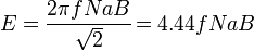
Other consistent systems of units can be used with the appropriate
conversions in the equation.
Many others have patents
on transformers.
[édit]
Pertimbangan parktis
[édit]
Klasifikasi
sirkuit
Standard symbols
Transformer with two windings and iron core.
Transformer with three windings.
The dots show the relative winding
configuration of the windings.
Step-down or step-up transformer.
The symbol shows which winding has more turns,
but does not usually show the exact ratio.
Transformer with electrostatic screen,
which prevents capacitive
coupling between the windings.
[édit]
Karugian
An ideal transformer would have no losses, and would therefore be 100%
efficient. In practice, energy is dissipated due both to the resistance
of the windings known as copper
loss or I2 R loss, and to magnetic effects primarily attributable
to the core (known as iron
loss measured in watts per pound). Transformers are, in general, highly
efficient. Large power transformers (over 50 MVA) may attain an efficiency as
high as 99.75%. Small transformers, such as a plug-in "power brick" used to
power small consumer electronics, may be less than 85% efficient.
Transformer losses arise from:
Current flowing through the windings causes resistive heating of the
conductors (I2 R loss). At higher frequencies, skin
effect and proximity
effect create additional winding resistance and losses.
Induced eddy
currents circulate within the core, causing resistive heating. Silicon is
added to the steel to help in controlling eddy currents. Adding silicon also has
the advantage of stopping aging of the electrical steel that was a problem years
ago.
Each time the magnetic field is reversed, a small amount of energy is lost to
hysteresis
within the magnetic core. The amount of hysteresis is a function of the
particular core material.
Magnetic flux in the core causes it to physically expand and contract
slightly with the alternating magnetic field, an effect known as magnetostriction.
This in turn causes losses due to frictional heating in susceptible ferromagnetic
cores.
In addition to magnetostriction, the alternating magnetic field causes
fluctuating electromagnetic forces between the primary and secondary windings.
These incite vibrations within nearby metalwork, creating a familiar humming or
buzzing noise, and consuming a small amount of power.
Not all the magnetic field produced by the primary is intercepted by the
secondary. A portion of the leakage
flux may induce eddy currents within nearby conductive objects, such as the
transformer's support structure, and be converted to heat.
Large power transformers may be equipped with cooling fans, oil pumps or
water-cooled heat exchangers designed to remove the heat caused by copper and
iron losses. The power used to operate the cooling system is typically
considered part of the losses of the transformer.
[édit]
Operasi dina frékuénsi nu béda
The equation shows that the EMF of a transformer at a given flux density
increases with frequency. By operating at higher frequencies, transformers can
be physically more compact without reaching saturation,
and a given core is able to transfer more power. However, other properties of
the transformer such as losses due to the core and skin-effect also increase
with frequency. Generally, operation of a transformer at it's designed voltage
but at a higher frequency than will lead to reduced magnetising (no load
primary) current. At a frequency lower than the design value, with the rated
voltage applied, the magnetising current may increase to an excessive level.
Steel cores develop a larger hysteresis loss due to eddy
currents as the operating frequency is increased. Ferrite, or thinner steel
laminations for the core are typically used for frequencies above 1kHz. The
thinner steel laminations serve to reduce the eddy currents. Some types of very
thin steel laminations can be ran up to 10 kHz or more. Ferrite is used in
higher frequencies up to the VHF band and beyond. Aircraft traditionally use 400
Hz power systems since the slight increase in thermal losses is more than offset
by reduced weight. Military gear includes 400 Hz (and other frequencies) to
supply power for radar
or servomechanisms.
Flyback
transformers are built using ferrite cores. They supply high voltage to the
CRTs
at the frequency of the horizontal oscillator. In the case of television sets,
this is about 15.7kHz. It may be as high as 75 - 120kHz for high-resolution
computer monitors.
Switching
power supply transformers usually operate between 50-1000 kHz. The tiny
cores found in wristwatch backlight
power supplies produce audible sound (about 1 kHz).
Operation of a power transformer at other than its design frequency may
require assessment of voltages, losses, and cooling to establish if safe
operation is practical. For example, transformers at hydroelectric
generating stations may be equipped with over-excitation protection, so-called
"volts per hertz" protection relays,
to protect the transformer from overvoltage at higher-than-rated frequency which
may occur if a generator loses its connected load.
[édit]
Construksi
[édit]
Inti waja
Gambar:Transformer.filament.agr.jpg
Laminated core transformer showing edge of laminations at top of unit.
Transformers for use at power or audio frequencies have cores made of many
thin laminations of silicon
steel. By concentrating the magnetic flux, more of it is usefully linked by
both primary and secondary windings. Since the steel core is conductive, it,
too, has currents induced in it by the changing magnetic flux. Each layer is
insulated from the adjacent layer to reduce the energy lost to eddy
current heating of the core. The thin laminations are used to reduce the
eddy currents, and the insulation is used to keep the laminations from acting as
a solid piece of steel. The thinner the laminations, the lower the eddy
currents, and the lower the losses. Very thin laminations are generally used on
high frequency transformers. The cost goes up when using thinner laminations
mainly over the labor in stacking them. A typical laminated core is made from
E-shaped and I-shaped pieces, leading to the name "EI transformer". There is
other types such as the C-core or "cut core" transformer. In the EI transformer,
the laminations are stacked in what is known as an interleaved fashion. This is
where the E and I pieces are staggered while stacking to reduce any gap. If a
gap is needed, all the E's are stacked on one side, and all the I's on the other
creating a gap.
The cut core or C-core is made by winding a silicon steel strip around a
rectangular form. After the required thickness is achieved, it is removed from
the form and the laminations are bonded together. It is then cut in two forming
two C shapes. The faces of the cuts are then ground smooth so they fit very
tight with a very small gap to reduce losses. To use a C-core, a coil is wound
which is then placed over a leg of one half of the core. The core is then
assembled by placing the two C halves together, and holding them closed by a
steel strap. In this type of core, the coil will be on one leg, and the other is
bare. There is shell type cores available which are similar to the EI cores.
A steel core's remanence
means that it retains a static magnetic field when power is removed. When power
is then reapplied, the residual field will cause a high inrush
current until the effect of the remanent magnetism is reduced, usually after
a few cycles of the applied alternating current. Overcurrent protection devices
such as fuses
must be selected to allow this harmless inrush to pass. On transformers
connected to long overhead power transmission lines, induced currents due to
geomagnetic disturbances during solar storms can cause saturation of the core,
and false operation of transformer protection
devices.
Distribution transformers can achieve low off-load losses by using cores made
with low loss high permeability silicon
steel and amorphous (non-crystalline) steel, so-called "metal
glasses" — the high cost of the core material is offset by the lower losses
incurred at light load, over the life of the transformer. In order to maintain
good voltage regulation, distribution transformers are designed to have very low
leakage
inductance.
Certain special purpose transformers use long magnetic paths, insert air
gaps, or add magnetic shunts (which bypass a portion of magnetic flux that would
otherwise link the primary and secondary windings) in order to intentionally add
leakage inductance. The additional leakage inductance limits the secondary
winding's short circuit current to a safe, or a controlled, level. This
technique is used to stabilize the output current for loads that exhibit negative
resistance such as electric
arcs, mercury
vapor lamps, and neon
signs, or safely handle loads that may become periodically short-circuited
such as electric arc welders. Gaps are also used to keep a transformer from
saturating, especially audio transformers which have a DC component added.
[édit]
Inti padet
Powdered iron
cores are used in circuits (such as switch-mode power supplies) that operate
above mains frequencies and up to a few tens of kilohertz.
These materials combine high magnetic permeability with high bulk
electrical resistivity.
At even higher, radio-frequencies (RF), other
types of cores made from non-conductive magnetic ceramic
materials, called ferrites,
are common. Some RF transformers also have moveable cores (sometimes called
slugs) which allow adjustment of the coupling coefficient (and bandwidth) of
tuned radio-frequency circuits.
[édit]
Inti udara
High-frequency transformers may also use air cores. These eliminate the loss
due to hysteresis
in the core material. Such transformers maintain high coupling efficiency (low
stray field loss) by overlapping the primary and secondary windings.
[édit]
Inti toroid

Various transformers. The top right is toroidal. The bottom right is from a
12 VAC wall wart supply.
Toroidal transformers are built around a ring-shaped core, which is made from
a long strip of silicon steel
or permalloy
wound into a coil, from powdered iron, or ferrite,
depending on operating frequency. The strip construction ensures that the grain
boundaries are optimally aligned, improving the transformer's efficiency by
reducing the core's reluctance.
The closed ring shape eliminates air gaps inherent in the construction of an EI
core. The cross-section of the ring is usually square or rectangular, but more
expensive cores with circular cross-sections are also available. The primary and
secondary coils are often wound concentrically to cover the entire surface of
the core. This minimises the length of wire needed, and also provides screening
to minimize the core's magnetic field from generating electromagnetic
interference.
Ferrite toroid cores are used at higher frequencies, typically between a few
tens of kilohertz to a megahertz, to reduce losses, physical size, and weight of
switch-mode
power supplies.
Toroidal transformers are more efficient than the cheaper laminated EI types
of similar power level. Other advantages, compared to EI types, include smaller
size (about half), lower weight (about half), less mechanical hum (making them
superior in audio amplifiers), lower exterior magnetic field (about one tenth),
low off-load losses (making them more efficient in standby circuits),
single-bolt mounting, and more choice of shapes. This last point means that, for
a given power output, either a wide, flat toroid
or a tall, narrow one with the same electrical properties can be chosen,
depending on the space available. The main disadvantages are higher cost and
limited size.
A drawback of toroidal transformer construction is the higher cost of
windings. As a consequence, toroidal transformers are uncommon above ratings of
a few kVA. Small distribution transformers may achieve some of the benefits of a
toroidal core by splitting it and forcing it open, then inserting a bobbin
containing primary and secondary windings.
When fitting a toroidal transformer, it is important to avoid making an
unintentional short-circuit
through the core. This can happen if the steel mounting bolt in the middle of
the core is allowed to touch metalwork at both ends, making a loop of conductive
material which passes through the hole in the toroid. Such a loop could result
in a dangerously large current flowing in the bolt.
[édit]
Beulitan
The wire of the adjacent turns in a coil, and in the different windings, must
be electrically insulated from each other. The wire used is generally magnet
wire. Magnet wire is a copper wire with a coating of varnish or some other
synthetic coating. Transformers for years have used Formvar
wire which is a varnished type of magnet wire.
The conducting material used for the winding depends upon the application.
Small power and signal transformers are wound with solid copper wire, insulated
usually with enamel,
and sometimes additional insulation. Larger power transformers may be wound with
wire, copper, or aluminum rectangular conductors. Strip conductors are used for
very heavy currents. High frequency transformers operating in the tens to
hundreds of kilohertz will have windings made of Litz
wire to minimize the skin effect losses in the conductors. Large power
transformers use multiple-stranded conductors as well, since even at low power
frequencies non-uniform distribution of current would otherwise exist in
high-current windings. Each strand is insulated from the other, and the strands
are arranged so that at certain points in the winding, or throughout the whole
winding, each portion occupies different relative positions in the complete
conductor. This "transposition" equalizes the current flowing in each strand of
the conductor, and reduces eddy
current losses in the winding itself. The stranded conductor is also more
flexible than a solid conductor of similar size. (see reference (1) below)
For signal transformers, the windings may be arranged in a way to minimise
leakage inductance and stray capacitance to improve high-frequency response.
This can be done by splitting up each coil into sections, and those sections
placed in layers between the sections of the other winding. This is known as a
stacked type or interleaved winding.
Windings on both the primary and secondary of power transformers may have
external connections (called taps) to intermediate points on the winding to
allow adjustment of the voltage ratio. Taps may be connected to an automatic,
on-load tap
changer type of switchgear
for voltage
regulation of distribution
circuits. Audio-frequency transformers, used for the distribution of audio to
public address loudspeakers, have taps to allow adjustment of impedance to each
speaker. A center-tapped transformer is often used in the output stage of an
audio power amplifier
in a push-pull
type circuit. Modulation transformers in AM transmitters are very similar.
Tapped transformers are also used as components of amplifiers, oscillators, and
for feedback
linearization of amplifier circuits.
[édit]
Isolasi
The turns of the windings must be insulated from each other to ensure that
the current travels through the entire winding. The potential difference between
adjacent turns is usually small, so that enamel insulation is usually sufficient
for small power transformers. In larger transformers additional layers of
insulation are used.
The transformer may also be immersed in transformer
oil that provides further to the insulation. The oil is primarily used to
cool the transformer. By cooling the windings, the insulation will not break
down as easy due to heat. To ensure that the insulating capability of the
transformer oil does not deteriorate, the transformer casing is completely
sealed against moisture ingress. Thus the oil serves as both a cooling medium to
remove heat from the core and coil, and as part of the insulation system.
Certain power transformers have the windings protected by a layer of epoxy
resin. This produces transformers suitable for damp or dirty environments, but
at increased manufacturing cost.
[édit]
Shielding
Where transformers are intended for minimum electrostatic coupling between
primary and secondary circuits, an electrostatic shield can be placed between
windings to reduce the capacitance between primary and secondary windings. The
shield may be a single layer of metal foil, insulated where it overlaps to
prevent it acting as a shorted turn, or a single layer winding between primary
and secondary. The shield is connected to earth ground.
Transformers may also be enclosed by magnetic shields, electrostatic shields,
or both to prevent outside interference from affecting the operation of the
transformer, or to prevent the transformer from affecting the operation of other
devices (such as CRTs
near the transformer).
[édit]
Paniis
Gambar:Transformer
01.jpg
Three phase dry-type transformer with cover removed; rated about 200 KVA, 480
V.
Small signal transformers do not generate significant amounts of heat. Power
transformers rated up to a few kilowatts rely on natural convective air cooling.
Specific provision must be made for cooling of high-power transformers.
Transformers handling higher power, or having a high duty cycle can be
fan-cooled.
Some dry transformers are enclosed in pressurized tanks and are cooled by nitrogen
or sulfur
hexafluoride gas.
The windings of high-power or high-voltage transformers are immersed in transformer
oil — a highly-refined mineral
oil, that is stable at high temperatures. Large transformers to be used
indoors must use a non-flammable liquid. Formerly, polychlorinated
biphenyl (PCB) was used as it was not a fire hazard in indoor power
transformers and it is highly stable. Due to the stability and toxic effects of
PCB byproducts, and its environmental accumulation, it is no longer permitted in
new equipment. Old transformers which still contain PCB should be examined on a
weekly basis for leakage. If found to be leaking, it should be changed out, and
the the old one professionally discarded. Today, nontoxic, stable silicone-based
oils, or fluorinated
hydrocarbons may be used where the expense of a fire-resistant liquid
offsets additional building cost for a transformer vault. Other less-flammable
fluids such as canola
oil may be used but all fire resistant fluids have some drawbacks in
performance, cost, or toxicity compared with mineral oil.
The oil cools the transformer, and provides part of the electrical insulation
between internal live parts. It has to be stable at high temperatures so that a
small short or arc will not cause a breakdown or fire. The oil-filled tank may
have radiators through which the oil circulates by natural convection. Very
large or high-power transformers (with capacities of millions of watts)
may have cooling fans, oil pumps and even oil to water heat
exchangers. Oil-filled transformers undergo prolonged drying processes,
using vapor-phase heat transfer, electrical self-heating, the application of a
vacuum,
or combinations of these, to ensure that the transformer is completely free of
water
vapor before the cooling oil is introduced. This helps prevent electrical
breakdown under load.
Oil-filled power transformers may be equipped with Buchholz
relays which are safety devices that sense gas build-up inside the
transformer (a side effect of an electric
arc inside the windings), and thus switches off the transformer.
Experimental power transformers in the 2 MVA range have been built with superconducting
windings which eliminates the copper losses, but not the core steel loss. These
are cooled by liquid nitrogen
or helium.
[édit]
Terminal
Very small transformers will have wire leads connected directly to the ends
of the coils, and brought out to the base of the unit for circuit connections.
Larger transformers may have heavy bolted terminals, bus bars or high-voltage
insulated bushings
made of polymers or porcelain. A large bushing can be a complex structure since
it must provide electrical insulation without letting the transformer leak oil.
[édit]
Lampiran
Small transformers often have no enclosure. Transformers may have a shield
enclosure, as described above. Larger units may be enclosed to prevent contact
with live parts, and to contain the cooling medium (oil or pressurized gas).
[édit]
Tipe trafo
[édit]
Autotrafo
- Artikel utama: Autotrafo
An autotransformer
has only a single winding, which is tapped at some point along the winding. AC
or pulsed voltage is applied across a portion of the winding, and a higher (or
lower) voltage is produced across another portion of the same winding. While
theoretically separate parts of the winding can be used for input and output, in
practice the higher voltage will be connected to the ends of the winding, and
the lower voltage from one end to a tap. For example, a transformer with a tap
at the center of the winding can be used with 230 volts across the entire
winding, and 115 volts between one end and the tap. It can be connected to a 230
volt supply to drive 115 volt equipment, or reversed to drive 230 volt equipment
from 115 volts. As the same winding is used for input and output, the flux in
the core is partially cancelled, and a smaller core can be used. For voltage
ratios not exceeding about 3:1, an autotransformer is cheaper, lighter, smaller
and more efficient than a true (two-winding) transformer of the same rating.
In practice, transformer losses mean that autotransformers are not perfectly
reversible; one designed for stepping down a voltage will deliver slightly less
voltage than required if used to step up. The difference is usually slight
enough to allow reversal where the actual voltage level is not critical.
By exposing part of the winding coils and making the secondary connection
through a sliding brush,
an autotransformer with a near-continuously variable turns ratio can be
obtained, allowing for very small increments of voltage.

Transformers in a tube amplifier. Output transformers are on the left. The
power supply toroidal transformer is on right.
歡迎來到Bewise
Inc.的世界,首先恭喜您來到這接受新的資訊讓產業更有競爭力,我們是提供專業刀具製造商,應對客戶高品質的刀具需求,我們可以協助客戶滿足您對產業的不同要求,我們有能力達到非常卓越的客戶需求品質,這是現有相關技術無法比擬的,我們成功的滿足了各行各業的要求,包括:精密HSS
DIN切削刀具、協助客戶設計刀具流程、DIN or JIS 鎢鋼切削刀具設計、NAS986 NAS965 NAS897 NAS937orNAS907 航太切削刀具,NAS航太刀具設計、超高硬度的切削刀具、醫療配件刀具設計、複合式再研磨機、PCD地板專用企口鑽石組合刀具、NSK高數主軸與馬達、專業模具修補工具-氣動與電動、粉末造粒成型機、主機版專用頂級電桿、PCD
V-Cut刀、捨棄式圓鋸片組、粉末成型機、主機版專用頂級電感、’汽車業刀具設計、電子產業鑽石刀具、木工產業鑽石刀具、銑刀與切斷複合再研磨機、銑刀與鑽頭複合再研磨機、銑刀與螺絲攻複合再研磨機等等。我們的產品涵蓋了從民生刀具到工業級的刀具設計;從微細刀具到大型刀具;從小型生產到大型量產;全自動整合;我們的技術可提供您連續生產的效能,我們整體的服務及卓越的技術,恭迎您親自體驗!!
BW Bewise Inc. Willy Chen
willy@tool-tool.com
bw@tool-tool.com www.tool-tool.com
skype:willy_chen_bw mobile:0937-618-190 Head &Administration Office
No.13,Shiang Shang 2nd St., West Chiu Taichung,Taiwan 40356 http://www.tool-tool.com /
FAX:+886 4 2471 4839 N.Branch 5F,No.460,Fu Shin North Rd.,Taipei,Taiwan S.Branch
No.24,Sec.1,Chia Pu East Rd.,Taipao City,Chiayi Hsien,Taiwan
Welcome to BW tool
world! We are an experienced tool maker specialized in cutting tools. We focus
on what you need and endeavor to research the best cutter to satisfy
users’ demand. Our customers involve wide range of industries,
like mold & die, aerospace, electronic, machinery, etc. We are professional
expert in cutting field. We would like to solve every problem from you. Please
feel free to contact us, its our pleasure to serve for you. BW product including: cutting
tool、aerospace tool
.HSS DIN Cutting
tool、Carbide end
mills、Carbide cutting
tool、NAS Cutting
tool、NAS986 NAS965 NAS897 NAS937orNAS907 Cutting Tools,Carbide end mill、disc milling cutter,Aerospace cutting
tool、hss
drill’Фрезеры’Carbide drill、High speed steel、Compound Sharpener’Milling cutter、INDUCTORS FOR PCD’CVDD(Chemical Vapor Deposition Diamond
)’PCBN (Polycrystalline Cubic
Boron Nitride) ’Core
drill、Tapered end mills、CVD Diamond Tools Inserts’PCD Edge-Beveling Cutter(Golden
Finger’PCD
V-Cutter’PCD Wood
tools’PCD Cutting
tools’PCD Circular Saw
Blade’PVDD End
Mills’diamond
tool. INDUCTORS FOR PCD .
POWDER FORMING MACHINE
‘Single Crystal Diamond
‘Metric end
mills、Miniature end
mills、Специальные
режущие инструменты ‘Пустотелое сверло
‘Pilot
reamer、Fraises’Fresas con mango’ PCD (Polycrystalline
diamond) ‘Frese’POWDER FORMING
MACHINE’Electronics cutter、Step drill、Metal cutting saw、Double margin drill、Gun barrel、Angle milling cutter、Carbide burrs、Carbide tipped cutter、Chamfering tool、IC card engraving cutter、Side cutter、Staple Cutter’PCD diamond cutter specialized in grooving
floors’V-Cut PCD
Circular Diamond Tipped Saw Blade with Indexable Insert’ PCD Diamond Tool’ Saw Blade with Indexable
Insert’NAS
tool、DIN or
JIS tool、Special tool、Metal slitting saws、Shell end mills、Side and face milling
cutters、Side chip
clearance saws、Long end
mills’end mill
grinder’drill
grinder’sharpener、Stub roughing end mills、Dovetail milling cutters、Carbide slot drills、Carbide torus cutters、Angel carbide end mills、Carbide torus cutters、Carbide ball-nosed slot
drills、Mould cutter、Tool
manufacturer.
Bewise Inc. www.tool-tool.com
ようこそBewise Inc.の世界へお越し下さいませ、先ず御目出度たいのは新たな
情報を受け取って頂き、もっと各産業に競争力プラス展開。
弊社は専門なエンド・ミルの製造メーカーで、客先に色んな分野のニーズ、
豊富なパリエーションを満足させ、特にハイテク品質要求にサポート致します。
弊社は各領域に供給できる内容は:
(1)精密HSSエンド・ミルのR&D
(2)Carbide Cutting
tools設計
(3)鎢鋼エンド・ミル設計
(4)航空エンド・ミル設計
(5)超高硬度エンド・ミル
(6)ダイヤモンド・エンド・ミル
(7)医療用品エンド・ミル設計
(8)自動車部品&材料加工向けエンド・ミル設計
弊社の製品の供給調達機能は:
(1)生活産業~ハイテク工業までのエンド・ミル設計
(2)ミクロ・エンド・ミル~大型エンド・ミル供給
(3)小Lot生産~大量発注対応供給
(4)オートメーション整備調達
(5)スポット対応~流れ生産対応
弊社の全般供給体制及び技術自慢の総合専門製造メーカーに貴方のご体験を御待ちしております。
Bewise Inc. talaşlı imalat sanayinde en fazla kullanılan ve üç eksende
(x,y,z) talaş kaldırabilen freze takımlarından olan Parmak Freze imalatçısıdır.
Çok geniş ürün yelpazesine sahip olan firmanın başlıca ürünlerini Karbür Parmak
Frezeler, Kalıpçı Frezeleri, Kaba Talaş Frezeleri, Konik Alın Frezeler, Köşe
Radyüs Frezeler, İki Ağızlı Kısa ve Uzun Küresel Frezeler, İç Bükey Frezeler vb.
şeklinde sıralayabiliriz.
BW специализируется в
научных исследованиях и разработках, и снабжаем самым высокотехнологичным
карбидовым материалом для поставки режущих / фрезеровочных инструментов для
почвы, воздушного пространства и электронной индустрии. В нашу основную
продукцию входит твердый карбид / быстрорежущая сталь, а также двигатели,
микроэлектрические дрели, IC картонорезальные машины, фрезы для гравирования,
режущие пилы, фрезеры-расширители, фрезеры-расширители с резцом, дрели, резаки
форм для шлицевого вала / звездочки роликовой цепи, и специальные нано
инструменты. Пожалуйста, посетите сайт www.tool-tool.com для получения
большей информации.
BW is specialized in
R&D and sourcing the most advanced carbide material with high-tech coating
to supply cutting / milling tool for mould & die, aero space and electronic
industry. Our main products include solid carbide / HSS end mills, micro
electronic drill, IC card cutter, engraving cutter, shell end mills, cutting
saw, reamer, thread reamer, leading drill, involute gear cutter for spur wheel,
rack and worm milling cutter, thread milling cutter, form cutters for spline
shaft/roller chain sprocket, and special tool, with nano grade. Please visit our
web www.tool-tool.com
for more info.
文章定位: